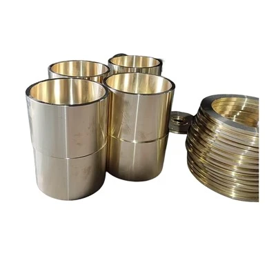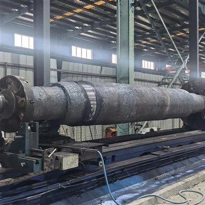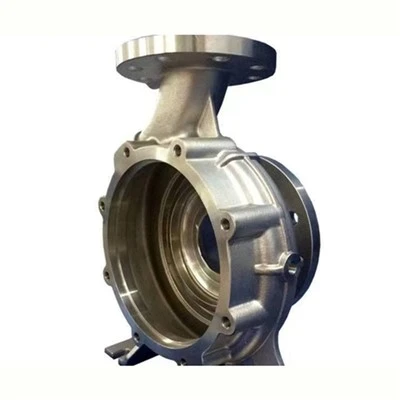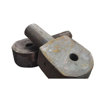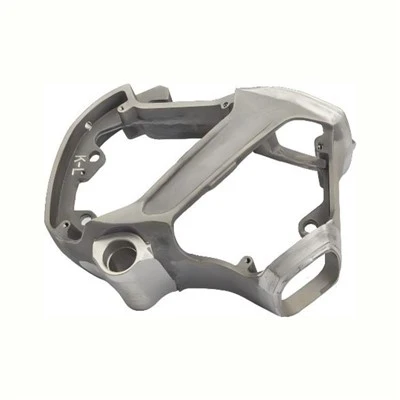


If you’ve ever stared at a CAD file for a mechanical assembly, second-guessing whether that copper alloy bushing you’re specifying will hold up under load or wear out too fast, you’re not alone. As a copper alloy bushings supplier, I field this question at least three times a week from engineers and maintenance managers across industries—from heavy agricultural equipment to precision robotics. Choosing the right bushing length isn’t just a technical detail; it’s the difference between a machine that runs for years without a hitch and one that goes down prematurely, costing thousands in downtime and replacement parts. Let’s break down what goes into this decision, with real-world context from decades of working with Copper Alloy Bushings for clients worldwide.
First, it helps to remember what a copper alloy bushing does: it’s a plain bearing that reduces friction between two moving metal surfaces, supporting radial (side-to-side) and sometimes axial (along the axis) loads. The length of that bushing directly impacts how evenly load is distributed across its surface, how much friction it generates, and how it handles misalignment—all critical factors that affect lifespan. Let’s start with the most foundational consideration: load type and magnitude.
Radial load is the most common force bushings handle, and for radial loads, the standard rule of thumb (that I’ve refined over years of designing custom bushings with precision casting) is the L/D ratio: length divided by diameter. For most general-purpose applications, the ideal L/D ratio falls between 0.8 and 1.5. What does that mean in practice? If you have a shaft with a 2-inch diameter, a bushing length between 1.6 and 3 inches works for most cases. But why does this ratio matter? If you go too low—say, an L/D of 0.5 on that 2-inch shaft—that means a 1-inch long bushing. The load will be concentrated on a tiny section of the bushing’s inner surface, leading to high contact pressure. That pressure can wear the bushing rapidly, especially if it’s a copper alloy that’s softer than the mating shaft (common for tin bronzes or leaded bronzes, our most popular Copper Alloy Bushings lines for general use). Too high an L/D, though—like 2.5 or higher—creates its own problems. The bushing will be long enough that the ends might catch on misaligned parts, or the extra length increases friction, leading to more heat buildup that can degrade the copper alloy’s properties over time.
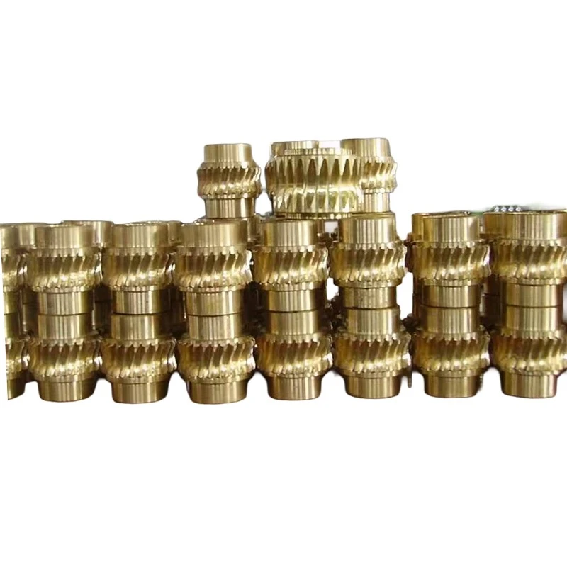
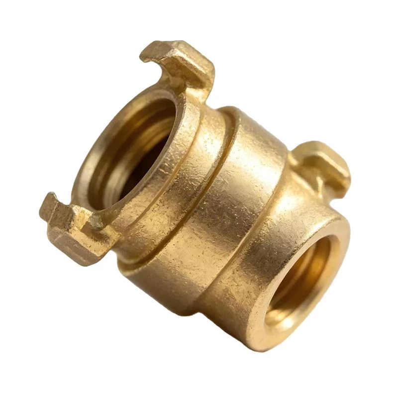
Wait, but that’s just the baseline. What about axial load? If your bushing is also supporting force along the shaft’s axis (think of a bushing in a linear actuator or a gear that slides along a splined shaft), the rules shift completely. For axial loads, we don’t use L/D; we focus on the contact area between the bushing’s face and the mating part. A longer bushing here would mean more surface area to distribute that axial force, which is great for heavy press-fit applications or parts that take repeated thrust impacts. But again, we can’t overdo it—too long a bushing for axial load increases the chance of edge loading when the part moves slightly, leading to uneven wear. I remember a client in the construction industry who once specified a 10-inch long bushing for a hydraulic ram’s axial load application. It wore out in 3 months because the length was too great, and the axial force was concentrated on the bushing’s outer edges. We switched it to a 6-inch long bushing, adjusted for axial contact pressure, and it’s still running 2 years later. That’s the kind of real-world testing we do, often adapting our Copper Alloy Precision Castings to tweak length and wall thickness for exact load needs.
Next, you have to account for misalignment. No machine is perfectly aligned, and that’s not a flaw—it’s a fact of engineering, especially in heavy equipment that vibrates or expands and contracts with temperature. When shafts are misaligned, the bushing can experience “tilting” load, where one end of the bushing carries more force than the other. How does length play into this? Shorter bushings handle misalignment better than longer ones, because a shorter bushing can flex (to a degree) to match the shaft’s angle without creating high edge pressure. That said, shorter bushings have lower load capacity, so there’s a tradeoff. For example, in agricultural tillers, which run in rough soil and experience constant vibration-induced misalignment, our standard recommendation is an L/D of 0.8 to 1.0, rather than 1.5, because it balances load capacity and misalignment tolerance. For applications with perfect alignment—like robotic arm joints in a controlled factory environment—you can push the L/D up to 1.5, taking advantage of the higher load capacity without worrying about misalignment wear.
Wear rate is another factor that ties directly to bushing length, and it’s not just about load. The relative sliding speed between the bushing and shaft matters too. If you have a bushing operating at high speeds, a longer bushing can help distribute the friction heat that builds up. The extra surface area dissipates heat better than a shorter bushing, which is why we make longer leaded bronze bushings for conveyor systems that run 24/7 at high speeds. But for slow-moving parts—like valve stems that only open and close a few times a minute—shorter bushings work just fine, since heat buildup is minimal. I once had a client in the HVAC industry who was using a 2-inch long bushing for a slow-moving damper shaft, but they were overheating the motor because the bushing was creating too much friction. We switched them to a 1.25-inch long bushing, adjusted the inner diameter to match, and motor temperature dropped by 15 degrees. That’s a clear example of how length directly impacts operational performance, beyond just wear or load.
Don’t forget about space constraints, either. This might seem like a given, but you’d be surprised how many engineers get so caught up in technical specs that they forget to check if their bushing will fit in the available space. If the assembly has only 1.5 inches of room for the bushing, an L/D of 1.5 on a 1-inch shaft would mean a 1.5-inch bushing—perfect. But if the shaft is 1.25 inches in diameter, 1.5 times that would be 1.875 inches, which is too long for the space. In that case, you have to adjust the L/D ratio lower, or sometimes switch to a different copper alloy with higher load capacity so you can use a shorter bushing without sacrificing performance. This is where our team’s expertise comes in—we don’t just sell Copper Alloy Machined Parts; we work with clients to balance technical needs with physical space, making sure every part fits and performs.
Another often-overlooked factor is lubrication. Bushings rely on a lubricant (oil, grease, or even dry lubricants for food-grade applications) to reduce friction and wear, and length affects how well that lubricant stays in place. A longer bushing holds lubricant better, as there’s more surface area to retain it, which is great for applications where relubrication is difficult—like parts in offshore drilling equipment, where maintenance is rare. But a longer bushing can also trap contaminants, like dirt or metal shavings, that get between the bushing and shaft. That’s why for dirty environments (construction, mining), we recommend slightly shorter bushings, since they’re easier to clean and don’t hold contaminants as easily. For food and beverage equipment, which requires frequent cleaning to prevent cross-contamination, we often use shorter bushings too—they’re faster to inspect and lubricate, and less likely to harbor bacteria in hard-to-reach gaps.
Let’s bring this all together with a quick example to make it concrete. Suppose you’re designing a water pump for a municipal water system. The shaft has a 1.5-inch diameter, carries 500 lbs of radial load, operates at 1,200 RPM (high speed), and needs to handle minor misalignment from pump vibration. What’s the right length? Let’s start with the L/D ratio: since misalignment is a factor, we’ll use a baseline L/D of 1.0, giving a 1.5-inch long bushing. But wait, it’s a high-speed application, so we might bump the length slightly to 1.75 inches (L/D ~1.17) to improve heat dissipation and lubricant retention. We’ll also use a tin bronze alloy, which has good corrosion resistance to water and is ideal for this kind of pump. If space was tight, and we only had 1.25 inches available, we’d use a higher-strength aluminum bronze instead, which can handle higher contact pressure in a shorter length, so we could get the same load capacity with a 1.25-inch bushing.
At the end of the day, there’s no one-size-fits-all answer to “what’s the right length for a copper alloy bushing.” It depends on load type and magnitude, misalignment, sliding speed, lubrication needs, space constraints, and even the environment the bushing will operate in. As a supplier, I’ve seen too many projects fail because of a poorly specified bushing length—whether it’s too long and wears out fast, or too short and can’t handle the load. That’s why our team doesn’t just send over a catalog of standard bushings; we work with every client to walk through their specific application, adjust specs, and even create custom parts when needed.
If you’re working on a project and aren’t sure what length copper alloy bushing you need, or you want to talk through custom options for your load, space, or environment, we’re here to help. Our team has decades of experience in copper alloy bearings, and we can guide you through every step of the process—from selecting the right alloy to finding the perfect length.
References
- Neale, M. J. (1995). Tribology Handbook: A Practical Guide to Lubrication, Friction and Wear. Butterworth-Heinemann.
- NASA. (2007). Bearing Design Handbook: Plain Bearings for Spacecraft and Launch Vehicles. National Aeronautics and Space Administration.
- American Society of Mechanical Engineers (ASME). (2018). B106.1M-2018: Plain Bearings - Measurement of Plain Bearing Performance. The American Society of Mechanical Engineers.
- Hutchings, I. M. (2016). Tribology: Friction and Wear of Engineering Materials (2nd ed.). CRC Press.