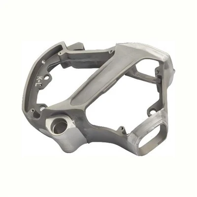


If you’ve ever walked through a facility with heavy machinery, you’ve seen reducer housings and pump housings doing critical work—though you might not have stopped to notice how different their manufacturing requirements are. As a supplier focused on reducer housing processing, I’ve spent years refining our approach for this specific component, and the gap between our work and pump housing processing is more than just a matter of size or shape. It comes down to core functional needs, material selection, tolerance specifications, machining processes, and quality control, all of which directly impact how each part performs in its intended environment. Let’s break down the key differences, because understanding these nuances is what sets reliable machining partners apart from those that only deliver parts that “sort of fit.”
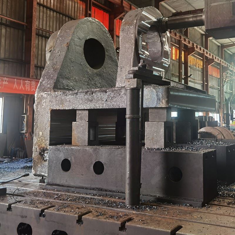
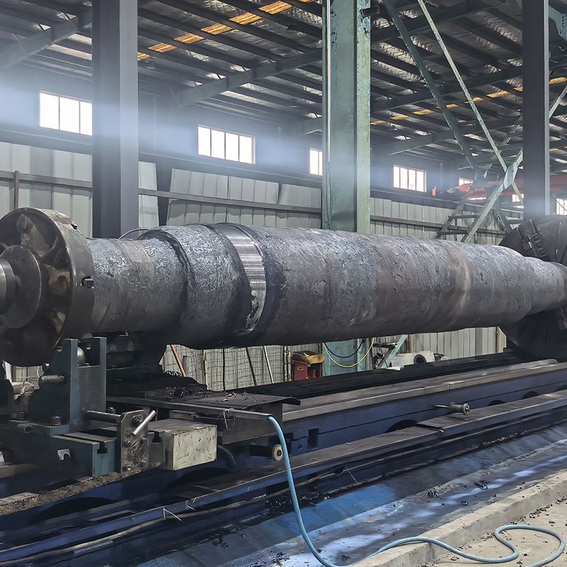
First, let’s ground this in purpose, because function drives every decision in processing. Reducer housings house gear sets that reduce rotational speed while increasing torque—think of the gearbox in a conveyor system, a mining crusher, or a wind turbine. That means the housing isn’t just a protective shell; it’s a load-bearing structure that must withstand extreme radial and axial forces from meshing gears, as well as the pressure of lubricating oil that circulates to cool and lubricate those gears. Pump housings, by contrast, contain impellers that move fluids (water, oil, chemicals, gas) at consistent flow rates. Their job is to create a sealed, smooth passage for fluid, so their primary stress is usually pressure from the fluid inside, not the shear of metal-on-metal gears. This functional split immediately shapes every step of the manufacturing process, starting with material selection.
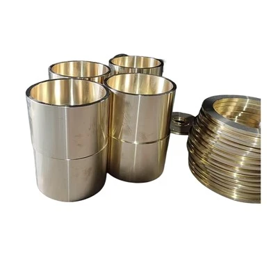
When I source materials for reducer housing processing, I almost exclusively work with cast iron (gray iron, ductile iron) or forged carbon steel. Gray iron’s high compressive strength and vibration-damping properties make it ideal for gear-driven loads—when a gear set runs at 1,000 RPM for 12 hours straight, vibration control prevents gear wear and extends the entire system’s lifespan. Ductile iron is another go-to for larger reducers, as its tensile strength holds up better to sudden shock loads, like when a conveyor slams into a heavy payload. For specialized applications (like offshore wind reducers that face saltwater corrosion), we might use alloy steel, but that’s rare for standard reducer housings. Pump housings, on the other hand, are far more likely to be made from cast aluminum, cast brass, or stainless steel. Aluminum’s lightweight, corrosion resistance, and ability to be machined into tight, smooth surfaces make it perfect for water pumps or automotive fuel pumps, where weight reduction and quick, consistent fluid flow matter more than extreme load bearing. Brass is used for low-pressure fluid pumps, like those in household plumbing, while stainless steel is reserved for chemical pumps that can’t handle rust. If you’re exploring how these materials translate to broader machining capabilities, you can check out Mechanical Parts Processing to see how different materials are tailored for specific industrial components.
Next, tolerance specifications are where the real precision differences show up. Reducer housings have two critical mating surfaces: the bore that holds the gear shaft bearings and the mounting face that connects to adjacent components. For reducer housings, these surfaces need tight geometric tolerances because even a 0.001-inch misalignment in the bearing bore can cause gear noise, premature bearing failure, or even gear seizure. We hold tolerances as tight as ±0.0005 inches for those bores, because gear-driven systems rely on perfect alignment to distribute torque evenly across all gear teeth. The mounting face also needs flatness within 0.0003 inches to ensure a leak-proof seal when bolted to the reducer’s mating component. Pump housings, by comparison, have far more flexible tolerances on structural surfaces—their main priority is smooth, consistent internal passageways for fluid, not precision for gear mating. While pump housings do need their impeller bores to align with the drive shaft, those tolerances are usually ±0.001 inches or wider, because fluid flow is less sensitive to tiny misalignments than metal gears. That’s not to say pump housings aren’t precise, but their precision is focused on fluid dynamics rather than load distribution. If you want to learn more about how tight tolerances are achieved across different housing types, CNC Machined Housing offers insights into precision machining standards for industrial enclosures.
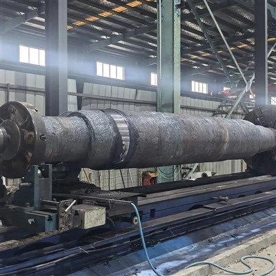
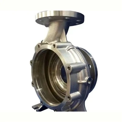
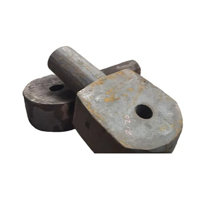
The machining processes themselves also diverge dramatically, even when both parts are made on similar CNC equipment. For reducer housing processing, we start with a rough casting (usually ductile or gray iron) and first perform heavy-duty rough milling to remove excess material from the outer walls and faces. The key here is high material removal rate—we need to shape the housing into its basic form before moving to precision operations, because castings have inconsistent wall thickness that can cause warping if machined unevenly. Once rough milling is done, we move to boring the bearing bores with a fine-tuned boring bar, often holding the workpiece on a fixture that locks it in place to eliminate vibration during machining. We also drill and tap dozens of mounting holes for gear shafts, oil drains, sight glasses, and lubrication ports—each hole’s position has to be aligned within tight tolerances to ensure the gear system works. For pump housings, the machining process is more focused on surface finish and fluid passage geometry. Most pump housings are die cast, so the basic shape is already near-net, meaning less material removal is needed. The primary operations are CNC milling to smooth the internal impeller chamber and CNC turning for the bore that holds the impeller shaft. Surface finish is critical here—we aim for a Ra value of 1.6 or lower on internal fluid passages to reduce friction and prevent fluid turbulence, which would lower pump efficiency. That’s why CNC Machining Of Die Castings is often the go-to method for pump housings, as die casting produces the smooth base surface that cuts down on post-machining finishing work.
Quality control is another area where the two processes differ, rooted in their functional risks. For reducer housings, a failure is catastrophic: if a gear bearing bore warps or a mounting hole is misaligned, the entire reducer can seize, shutting down a conveyor system, mining operation, or wind turbine for days. So our quality checks include CMM (coordinate measuring machine) scans of every critical mating surface, ultrasonic testing to check for hidden voids in the casting that could fail under load, and pressure testing for the oil passageways to ensure no leaks. We also perform run-out tests on the bearing bores, because even tiny run-out will cause gear wear over time. For pump housings, failure is less system-critical (though still costly), so quality checks focus on pressure testing of the fluid chamber to ensure it can hold the required fluid pressure, and leak testing to make sure no fluid escapes. CMM scans for pump housings are less frequent, only required for high-pressure or specialty applications, because their structural stresses are lower. If you’re looking for a broader overview of quality-focused machining, CNC Machined Parts gives a breakdown of how different components are inspected for performance.
Over the years, I’ve seen shops try to treat reducer housing processing like pump housing processing, and it almost always leads to problems. A manufacturer who uses low-tolerance machining for a reducer housing might deliver a part that fits the assembly line, but it will fail under load within a few months, causing costly downtime. Conversely, a shop that uses the high-load machining approach for pump housings will produce a part that’s unnecessarily heavy and expensive, with tighter tolerances than the pump actually needs, driving up costs without adding value. The sweet spot comes when you match every step of processing to the component’s intended use case: for reducers, load bearing, vibration control, and gear alignment are non-negotiable; for pumps, fluid dynamics, corrosion resistance, and smooth passageways take priority.
Another key point is material consistency, which is a make-or-break factor for both processes but for different reasons. For reducer housings, ductile iron castings need consistent carbon content and grain structure to ensure uniform strength across the entire housing—if one section is softer than others, it can deform under gear load. For pump housings, aluminum castings need uniform alloy content to ensure consistent corrosion resistance, especially if they’re used for potable water or food-grade fluids. If you’re working on a project that requires custom parts, Aluminum Alloy Non Standard Parts can show how tailored material selection supports different component needs, whether load-bearing or fluid-focused.
As a reducer housing processing specialist, our whole business is built on mastering these differences. We don’t just machine parts—we design our processes around the unique demands of gear-driven systems, using materials, tolerances, and machining techniques that prioritize long-term, reliable performance under extreme loads. If you’re working on a project that requires high-quality reducer housings, or if you want to learn more about how these processes fit into your industrial operations, we’re here to help. Our team has decades of experience matching machining solutions to specific application needs, and we’re ready to discuss how we can support your next project.
References
- Design of Machine Elements, 5th Edition, R.S. Khurmi, J.K. Gupta, S. Chand and Company Limited, 2005, pp. 124-138 (Covering load-bearing requirements for gear housings)
- Manufacturing Processes for Engineering Materials, 7th Edition, Serope Kalpakjian, Steven R. Schmid, Pearson Education, 2014, pp. 567-592 (Covering CNC machining tolerances and material selection for industrial components)
- Pump Handbook, 4th Edition, Igor J. Karassik, Joseph P. Messina, Paul Cooper, Pere H. Crawshaw, McGraw-Hill Education, 2008, pp. 312-327 (Covering fluid dynamics and processing requirements for pump housings)
- Cast Iron Engineering Handbook, American Foundry Society, 2019, pp. 219-235 (Covering material properties and machining best practices for gear housings)